sexta-feira, 23 de agosto de 2013

gSmart Mini Macro Lens

This camera hack is one of those that are easy to make and useful, I had an old gSmart mini camera and a macro lens and the idea was replace the original lens with the macro one and add some white led´s around the lens.
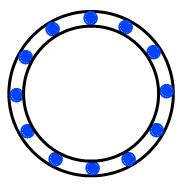
I started by cracking the old lens with a drill (all so needed larger hole) and glued the lens on to the screw, next I cut some foam to hold the white led's frame, this frame was made with copper wire molded on a 2euro coin and weld the led´s on it, finally I glued everything on the foam and secure the foam on the lens


 The led's are powered directly from the usb port because the current draw and easy connection, they are turn on by the power led, the below schematic is an example, since I did this hack some time ago and now I don´t remember the exact components.

As final aspect it didn't look good and is a little fragile and the camera needs to be very stable or the image will get out of focus.


but for a 25euro camera it's not bad I guess


As for the software I used Vision GS private Edition, but any webcam software will do the job.


sábado, 5 de janeiro de 2013

pro59801 lcd module hack

Currently I´m designing a power supply based on the well known  LM317 voltage regulator and needed a lcd module to show the voltage and current values. Some time ago, a friend give me some PRO59801 pinpad lcd modules which is a module based on the KS0713 controller. The problem is, that this module, has an 8bit parallel interface and I´m using a low pin count pic micro. After reading the KS0713 datasheet, I fount that this controller has a serial interface that can be selected via HW pin, also the controller is on a flex cable that connects the pcb to the glass, a search took me to an BP12864C lcd/controller solution again reading the datasheet found the pin that selects the serial/parallel interface. 

The module with the original connection

1 - GND
2 - VCC
3 - NC
4  - /RST
5  - /CS1
6  - RS
7  - RW_WR
8  - E_RD
9-14  DB0-DB5
DB6 - CLK
DB7 - SID
17 - led+
18 - led-


Originaly the PS pin is connected to VDD by the track marked by the red circule, just needed to cut it and connect the PS pin to GND, luckily the next pin was already conected to GND so only had to make the connection marked by the yellow circule.


Here is the final work

The power supply still is in development this is a test version, todo is the current adjustment and dummy load