domingo, 9 de agosto de 2015

Android PSU

Hi there, this time I bring an update of the Dummy Load/PSU, since this project was intended to use an Android tablet I leave some information and pictures of the progress made.

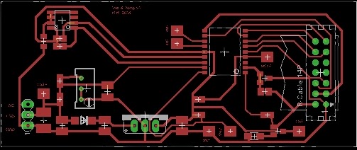
This project was made modular composed by 3 boards,  analog board, interface board and main control (Android tablet). This was made like this because I had some boards with a pic micro that also could control the analog board as in first design and to reduce the cost of the analog board.

The boards are connected according the diagram, as show the tablet communicates with the interface board via I2C bus that also is used by the tablet for reading the RTC. The interface board controls the analog board by two PWM signals one for current and the other for voltage, a digital out select between PS and DL.
All analog voltages are read by the ADC in the interface board and sent to tablet when requested.


Here we can see all boards connected making charging an discharging tests on a Li-ion battery.


 On the software side things got complicated I started to using ADK based on Eclipse and creating a simple interface to communicate with the I2C bus.
Since java doesn't allow communications with i2c bus, I had to write the interface using JNI (java native interface) in C to make the bridge between the Android app and the hardware, all of this is only possible on a rooted device.

With the interface working all that the application had to do is send commands for reading an writing using the protocol bellow.


As data uses a maximum of 10bits the remaining bits of high order byte are used to control data flow this also allows control some IO pins.
This protocol uses 3 bytes for writing (example setting pwm value) as mentioned 10bits are written to the registers specified on the remaining 6bits of data high byte.
Before reading data the corresponding register must be set, so a prior write with the register address is needed, after that any read sequence will return data from the that register.

For the interface board I used a pic16f76, this pic as many others has a dedicated MSSP port that can be configure to operate as I2C slave device.

At start the device configures i2c port and start the control state machine. this machine handles all data received.


It starts on IDLE state an remains until a byte is received, on receive checks the received byte is the slave address or data.
If an address was received, next the R/W bit on the slave address is tested if set (Read Data) then data H byte is sent and state is now RDL.
On the Acknowledge of data H  from master, the device sends data L and enters on IDLE state.

As for characterization curves of the output voltage, they are not that great as the graph shows, but keeping in mind that all parts are low end and no care on stability was taken this project works as expected


All project files are on git and design here


quinta-feira, 17 de abril de 2014

Dummy Load / Digital PSU

A power supply is must have for any electronic project but some times a dummy load is also useful. So, I started to design a power with a dummy load option based on this specs.

Power supply
Vout: 2.5V - 15V
Iout:  0A - 1A

Dummy load
0 - 1A

The power supply is based on the LM317 voltage regulator it goes from a minimum output of 1.2V to 30V at 1.5A, as for the dummy load see the video from  Dave's  he explains how it works.

The below schematic is only the analog circuit and it has two working modes, power supply and adjustable load, this modes are selected by a relay that switches the output pins connections in this configurations

Power supply                Adjustable Load
B+ -> LM317              B+ -> Mosfet
B- -> Mosfet                B- -> GND


The working principle for the voltage ajdjustment is very basic, a pwm signal is applied to the non inverting input of the OA and this one creates a reference voltage on the adj pin of the LM317
For the current adjustment it uses the same principle but is better explained on Dave's video 

For the digital circuit I used an PIC16F73, this mcu is used to generate two pwm signals, read three analog inputs and display information on a spi lcd.
On the software side I kept it simple as the final project is intend to use a an Android tablet instead of the pic and lcd, but for now on power mode it displays Voltage, Current and preset's, in load mode it displays Voltage, Current and Power it also plots a small graphic with the discharge curve.

Power supply mode, charging Li-ion battery (in this image battery is already charged)


Load mode, discharging Li-ion battery @3W


The pcb was designed with eagle and manufactured by OSH Park as this is rev 1 it has some issues like the relay footprint is wrong and diodes footprint is small, on the power dissipation side the heat sink is too small and should use an TO-220 mosfet instead of three so-8 mosfet


project files can be found here


segunda-feira, 24 de fevereiro de 2014

BMW bike Temperature and voltage indicator

This was a personal request from my boss to his bike, he notice that an empty space in the dash and ask me to see if I could add an temperature and voltmeter indicator, as I check the space I realize it was the size off an standard  2x16 Alphanumeric lcd and it could be easily fit. In the first approach I used an themistor and found out it was a bit unstable and not very accurate, for my second attempt i wanted a chip solution and the easy way was the DS1721. After having all components selected I draw the schematic and pcb, and it is simple circuit based on a pic16f819, the working principle is very basic for measuring the temperature it reads the data via i2c bus and for the voltage it reads an analog input connected to a voltage divisor


After assemble the circuit, I started the software and realize that the 5v form the regulator were good for analog reference and didn't assemble the TL431, all was working fine until the connection off the lcd backligth, I hadn't consider the current consumption and as result the magic smoke from the regulator and transistor, to solve this I had to connect a dedicated regulator for the backligth.


sexta-feira, 23 de agosto de 2013

gSmart Mini Macro Lens

This camera hack is one of those that are easy to make and useful, I had an old gSmart mini camera and a macro lens and the idea was replace the original lens with the macro one and add some white led´s around the lens.
I started by cracking the old lens with a drill (all so needed larger hole) and glued the lens on to the screw, next I cut some foam to hold the white led's frame, this frame was made with copper wire molded on a 2euro coin and weld the led´s on it, finally I glued everything on the foam and secure the foam on the lens


 The led's are powered directly from the usb port because the current draw and easy connection, they are turn on by the power led, the below schematic is an example, since I did this hack some time ago and now I don´t remember the exact components.

As final aspect it didn't look good and is a little fragile and the camera needs to be very stable or the image will get out of focus.


but for a 25euro camera it's not bad I guess


As for the software I used Vision GS private Edition, but any webcam software will do the job.


sábado, 5 de janeiro de 2013

pro59801 lcd module hack

Currently I´m designing a power supply based on the well known  LM317 voltage regulator and needed a lcd module to show the voltage and current values. Some time ago, a friend give me some PRO59801 pinpad lcd modules which is a module based on the KS0713 controller. The problem is, that this module, has an 8bit parallel interface and I´m using a low pin count pic micro. After reading the KS0713 datasheet, I fount that this controller has a serial interface that can be selected via HW pin, also the controller is on a flex cable that connects the pcb to the glass, a search took me to an BP12864C lcd/controller solution again reading the datasheet found the pin that selects the serial/parallel interface. 

The module with the original connection

1 - GND
2 - VCC
3 - NC
4  - /RST
5  - /CS1
6  - RS
7  - RW_WR
8  - E_RD
9-14  DB0-DB5
DB6 - CLK
DB7 - SID
17 - led+
18 - led-


Originaly the PS pin is connected to VDD by the track marked by the red circule, just needed to cut it and connect the PS pin to GND, luckily the next pin was already conected to GND so only had to make the connection marked by the yellow circule.


Here is the final work

The power supply still is in development this is a test version, todo is the current adjustment and dummy load

domingo, 19 de fevereiro de 2012

extractor

Every electronic lab needs a fumes extractor, so as i don't intend to buy one for the lab i made one, all started when found a "fan blower" from a server system, since this fans are system specific i had to do some reverse engineering, started to open the fan case tho see what was inside, what i found was a very robust system, the fan itself is made from aluminium the board has a nice layout were the air flow cool the power components, as the motor is a brushless i expected to find a brushless controller on the board and also found a pic16f88, the BLDC is a ML4425 with a few control pins that were connected to the pic, so the only thing i had to do was tho write my own control sw, the result was a very powerful fume extractor that work very nice.


domingo, 25 de setembro de 2011

Blueboard-LPC1768-H hack

Some time ago I was looking for a nice board for developing, browsing HaD I found review of a cheep cortex-m3 board, pleased with the specs, I order one form NGX site, when the board arrived it looked like this


After uploading a blink program I notice that all led's were a boring red, and replaced one by a green and other by a blue one, also remove the DC input jack since i was planing of using the power from usb port


after that came an lcd wtih messy conections 


navigation buttons


 sd card and accelerometer


and lots of coding, here a 2D minecraft example


for development I'm using a usb bootloader, Code Sourcery G++ lite and programme's notepad.