Power supply
Vout: 2.5V - 15V
Iout: 0A - 1A
Dummy load
0 - 1A
The power supply is based on the LM317 voltage regulator it goes from a minimum output of 1.2V to 30V at 1.5A, as for the dummy load see the video from Dave's he explains how it works.
The below schematic is only the analog circuit and it has two working modes, power supply and adjustable load, this modes are selected by a relay that switches the output pins connections in this configurations
Power supply Adjustable Load
B+ -> LM317 B+ -> Mosfet
B- -> Mosfet B- -> GND
The below schematic is only the analog circuit and it has two working modes, power supply and adjustable load, this modes are selected by a relay that switches the output pins connections in this configurations
Power supply Adjustable Load
B+ -> LM317 B+ -> Mosfet
B- -> Mosfet B- -> GND
The working principle for the voltage ajdjustment is very basic, a pwm signal is applied to the non inverting input of the OA and this one creates a reference voltage on the adj pin of the LM317
For the current adjustment it uses the same principle but is better explained on Dave's video
For the current adjustment it uses the same principle but is better explained on Dave's video
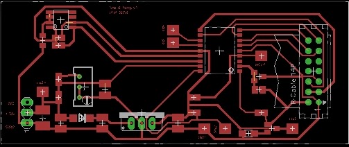
For the digital circuit I used an PIC16F73, this mcu is used to generate two pwm signals, read three analog inputs and display information on a spi lcd.
On the software side I kept it simple as the final project is intend to use a an Android tablet instead of the pic and lcd, but for now on power mode it displays Voltage, Current and preset's, in load mode it displays Voltage, Current and Power it also plots a small graphic with the discharge curve.
Power supply mode, charging Li-ion battery (in this image battery is already charged)
Load mode, discharging Li-ion battery @3W
project files can be found here


